Develop compute and control peripherals on one board
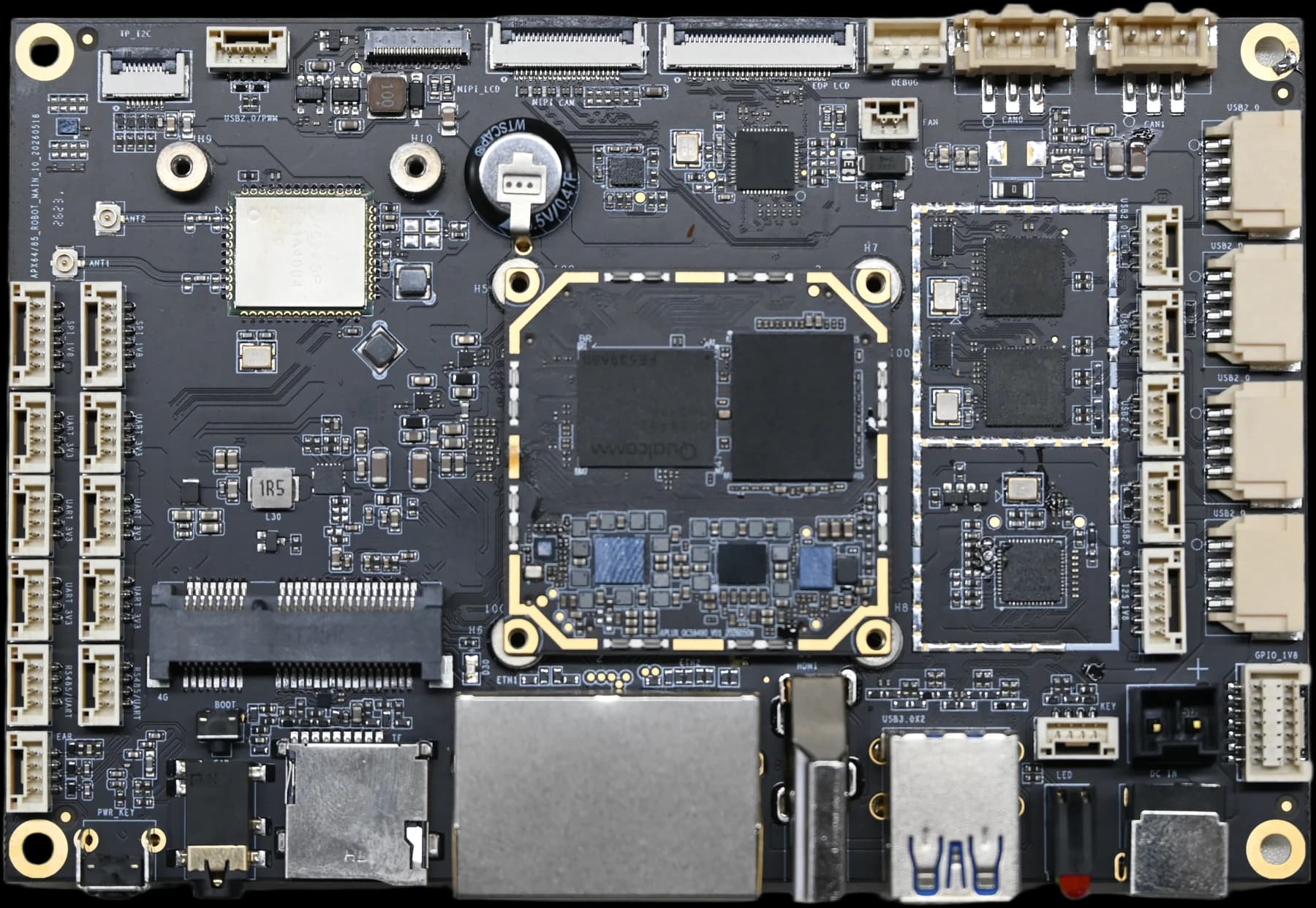
Rhino Core Q64 handles local computation; the carrier exposes CAN, RS485, UART and GPIO for controllers and industrial peripherals.

Industrial and robotics development board
Connect AI compute to equipment in the field
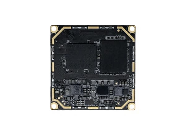
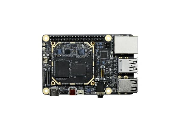
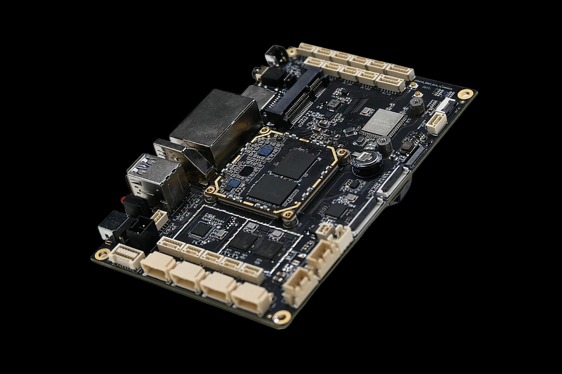
Combines a Rhino Core Q64 module with a companion carrier board. Dual Gigabit Ethernet, dual CAN, dual RS485 and display and vision interfaces support the transition from model evaluation to device integration.
12 TOPS
Maximum AI performance (INT8, dense)
Dual CAN + dual RS485
Industrial equipment connectivity
Dual Gigabit Ethernet
Wired Ethernet
135 × 90 mm
Carrier PCB dimensions
Match the compute platform to your device tasks, models, peripherals and product form factor.
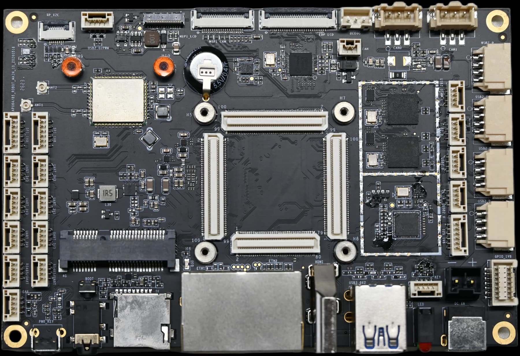
Rhino Core Q64 handles local computation; the carrier exposes CAN, RS485, UART and GPIO for controllers and industrial peripherals.
Two Gigabit RJ45 ports support equipment and upstream network integration; projects define network topology and application protocols.
Dual 4-lane MIPI CSI with HDMI, eDP, MIPI DSI and a dedicated touch interface supports vision and human-machine interaction projects.
Use an Ubuntu BSP matching the module and carrier configuration, together with AI tools for model adaptation, interface validation and application integration.
Locate connectors on the hardware and plan device connections around your peripherals.
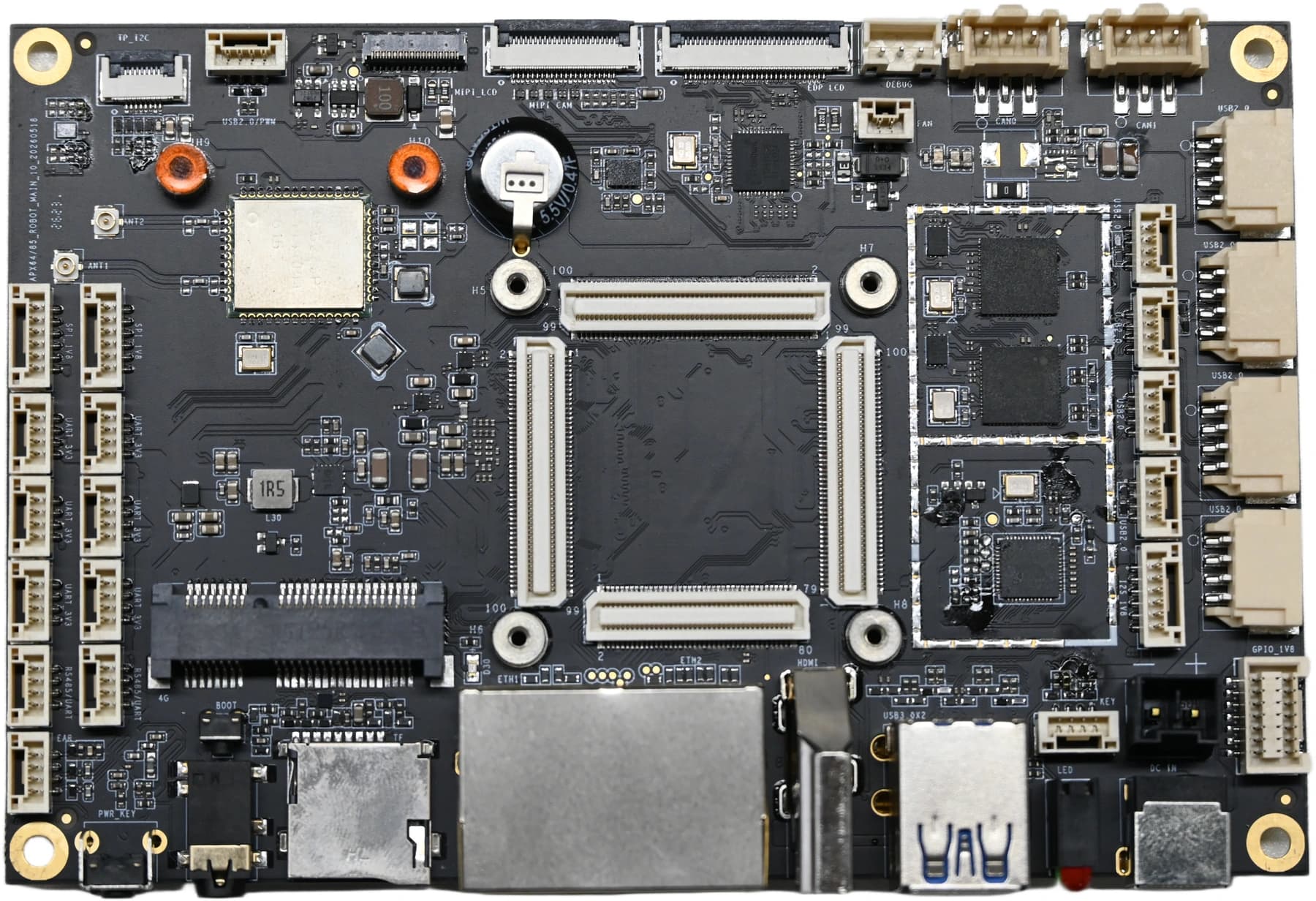
Select a number or interface name for connection details. Refer to the specification for pin assignments, voltage levels and multiplexing.
J1 DC jack and J2 power header: DC 10–24 V; recommended 12 V / 3 A.
Choose device workloads and integration paths based on platform capabilities and this model's interfaces.
Qualcomm Dragonwing QCS6490
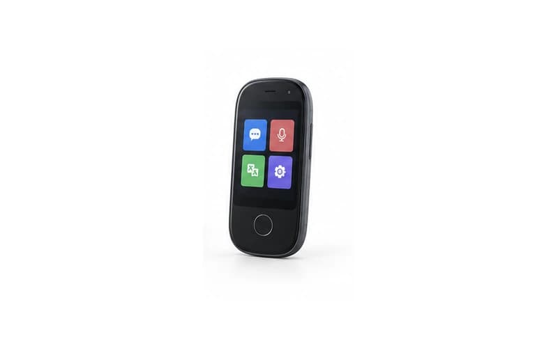
Combine touch interaction, image capture and local recognition in portable terminals for inspection, warehousing and field operations.
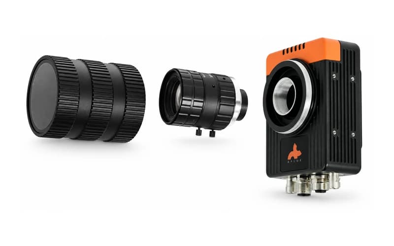
Integrate capture, recognition and result output on the device for detection, counting and status recognition tasks.
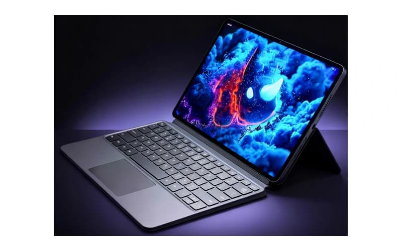
Connect displays, touch input, cameras and business systems to support industry user interfaces and local intelligent interaction.
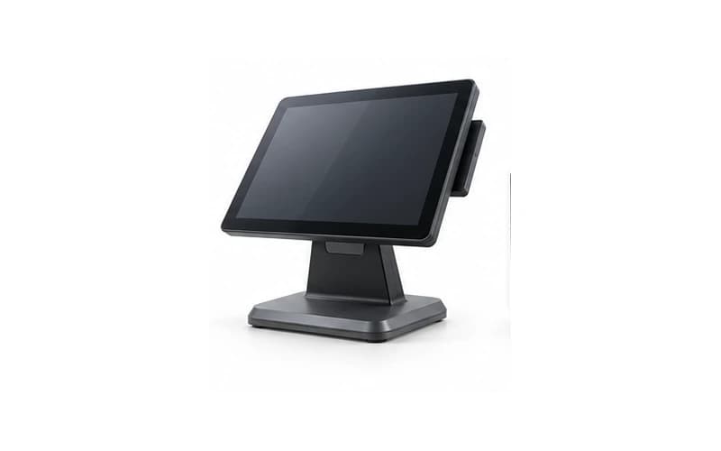
Combine scanning, displays and networking for checkout, self-service and in-store information terminals.
Device images illustrate application directions; peripherals, enclosure design and software require project-specific integration.
Configurations below follow the industrial and robotics development board documentation. Module capabilities and physically exposed board interfaces are distinguished.
| Assembly | Rhino Core Q64 + A8550PZ1-COM6490 carrier board |
|---|---|
| Compute platform | Qualcomm Dragonwing QCS6490 |
| Process | 6 nm |
| CPU | Octa-core Qualcomm Kryo 670, up to 2.7 GHz |
| NPU | Qualcomm Hexagon 770 |
| AI performance (INT8, dense) | Up to 12 TOPS(INT8, dense) |
| GPU | Qualcomm Adreno 643, up to 812 MHz |
| Memory | 4 GB / 8 GB LPDDR5, depending on model |
| Storage | 64 GB eMMC 5.1 |
| Camera | 2 × 4-lane MIPI CSI, 22-pin FPC, up to 2.5 Gbps/lane |
|---|---|
| HDMI | Standard Type-A, up to 4K@60Hz output |
| Display expansion | 30-pin eDP + 31-pin 4-lane MIPI DSI |
| Touch | TP (Touch Panel): 8-pin FPC, I²C, 1.8 V signals |
| Video decoding | Platform maximum 4K@60fps |
| Video encoding | Platform maximum 4K@30fps |
| USB-A | 2 × USB 3.0 Host sharing 5 Gbps upstream bandwidth |
|---|---|
| Internal USB | 8 × USB 2.0 Host, plus 1 SOM-native USB 2.0 (J53) |
| USB-C | USB 2.0 OTG for communication and supported flashing procedures |
| Ethernet | 2 × 10/100/1000 Mbps RJ45 |
| Wireless | AP6275P;Wi-Fi 6 + Bluetooth 5.3 |
| CAN | 2 × CAN supporting CAN 2.0B / CAN FD |
| RS485 | 2 channels with onboard 120Ω termination resistors |
| UART | 6 × 3.3 V TTL UART + dedicated debug port |
| GPIO | J36: 10 × 1.8 V GPIO |
| Expansion | USB 4G module interface in a Mini-PCIe form factor; PCIe SSDs are not supported |
| Operating system | Ubuntu 24.04 LTS with companion BSP |
|---|---|
| Power | DC 10–24 V; recommended 12 V / 3 A, through the DC jack or power connector |
| Carrier PCB | 135 × 90 mm, ±0.5 mm; board thickness 1.6 mm ±10% |
| Module dimensions | 40 × 40 mm, BTB connection |
| Assembly height | Confirm against the module, heatsink, connectors and delivered assembly drawing |
| Operating temperature | -25 °C~+50 °C |
| Fan | 5 V output, up to 1 A |
AI figures are platform-rated peaks. Dense, sparse and FP16 figures are listed separately; actual performance depends on the model, precision, software and cooling. Input power ratings do not represent total board consumption. Accessories and system images depend on the delivered configuration.
Download Chinese and English product briefs and specifications for product configuration, interface definitions and device integration requirements.
Product overview, key capabilities and application directions.
PDF · ChineseDownload Chinese briefProduct overview, key capabilities and application directions.
PDF · EnglishDownload English briefInterface definitions, power requirements and mechanical dimensions.
PDF · ChineseDownload specificationSystem images, firmware, development guides and reference designs.
Share your model, peripheral, mechanical and system requirements to define the product and delivery configuration together.